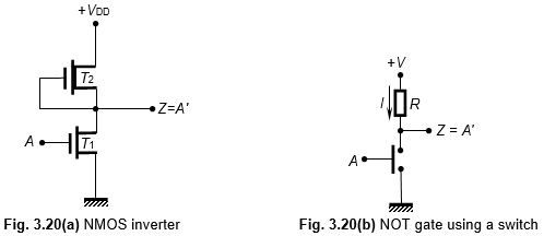
Nmos Inverter Circuit
Click here to go to the applet.
Nmos inverter circuit. An inverter circuit outputs a voltage representing the opposite logic level to its input. Its main function is to invert the input signal applied. As an example here is a nor gate implemented in schematic nmos. If either input a or input b is high logic 1 true the respective mos transistor acts as a very low resistance between the output and the negative supply forcing the output to be low logic 0 false.
146 the cmos inverter chapter 5 following interpretation of the inverter. Whenv in is high and equal to v dd the nmos transistor is on while the pmos is off. Cmos complementary metal oxide semiconductor technology which consists of both nmos and pmos and cmos logic gates includes not nand nor. N p.
Indian journal of pure applied physics vol. 48 february 2010 pp. Characteristics and applications m k mandal 1 b c sarkar 2. 4 paulo francisco butzen and renato perez ribas fig.
Cmos inverter short circuit current 6 this component represents less than 20 of the dynamic switching. Chapter 1 introduction to cmos circuit design jin fu li advanced reliable systems ares lab. Department of electrical engineering national central university.


