Mosfet H Bridge Inverter Circuit
In many applications we need to operate the motor in both directions clockwise and anticlockwise forward and back.
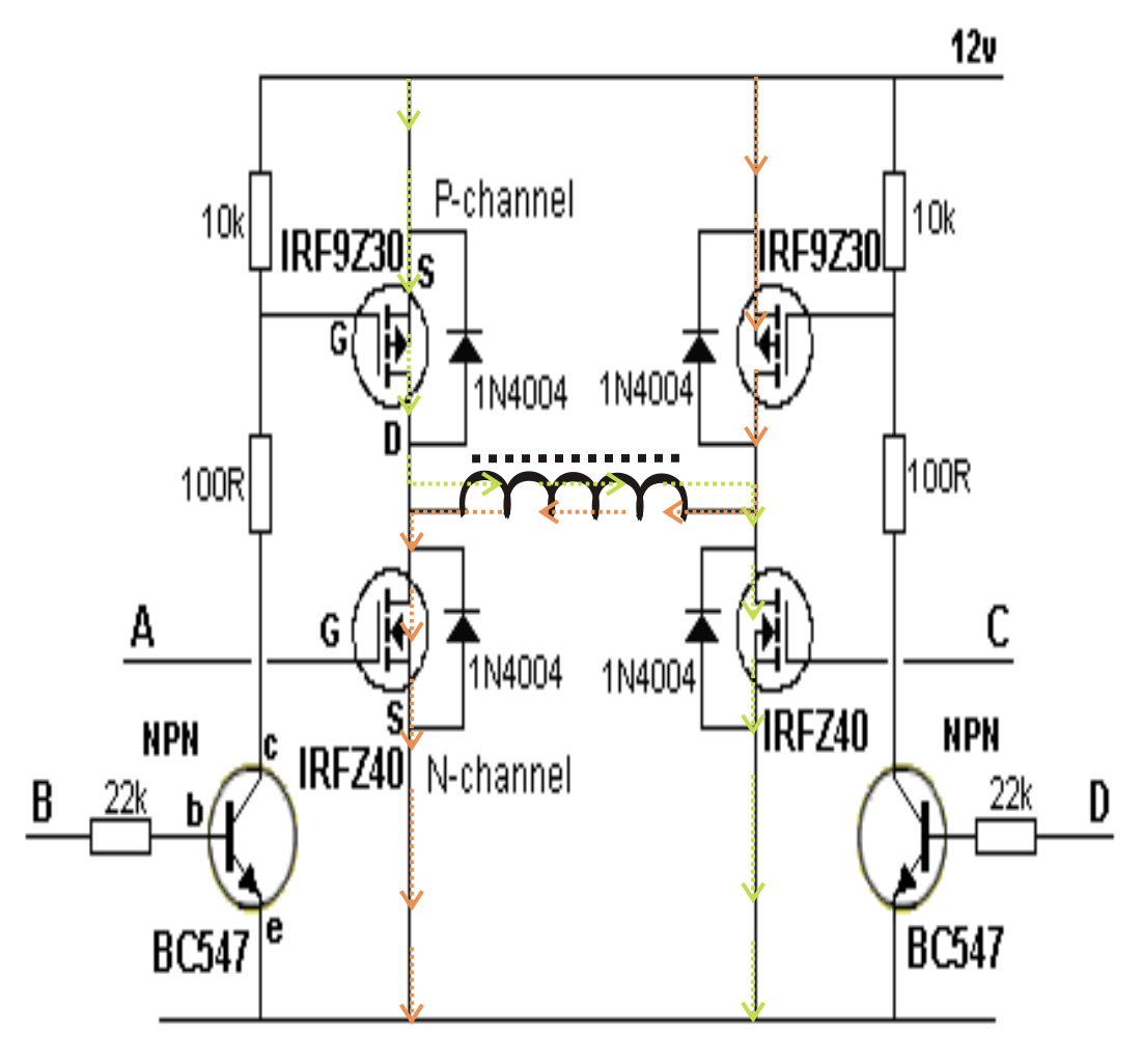
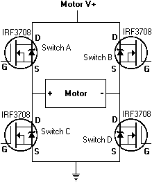
Mosfet h bridge inverter circuit. The circuit below shows a 3 phase inverter inverter circuit stage using h bridge mosfets configuration which receives the phase shifted pwms from the above stage and converts them into corresponding high voltage ac outputs for operating the connected 3 phase load normally this would be a 3 phase motor. The h bridge arrangement is generally used to reverse the polaritydirection of the motor but can also be used to brake the motor where the motor comes to a sudden stop as the motors terminals are shorted or to let the motor free run to a stop as the motor is effectively disconnected from the circuit. A power inverter or inverter is an electronic device or circuitry that changes direct current dc to alternating current ac. The input voltage output voltage and frequency and overall power handling depend on the design of the specific device or circuitry.
Simple pwm inverter circuit diagram using pwm chip sg3524 gallery of electronic circuits and projects providing lot of diy circuit diagrams robotics microcontroller projects electronic development tools. The h bridge is designed to drive a motor clockwise and anticlockwise. To reverse a motor the supply must be reversed and this is what the h bridge does. Bi direction control circuit for dc motor.
This circuit can control direction of a dc motor.


