Inverter Gate Circuit
The breadboard schematic of the circuit above is shown below.

Inverter gate circuit. Not being an expert on the use of the sg3524 i would do the following. Disconnect the jfet gates fron the circuit and measure the pull up voltage at pins 1114. A power inverter or inverter is an electronic device or circuitry that changes direct current dc to alternating current ac. The input voltage output voltage and frequency and overall power handling depend on the design of the specific device or circuitry.
This sg3525 inverter circuit is suitable for 100 watt applications. This article contains circuit diagram ic features working and video demonstration of the circuit. The tida 00195 reference design consists of a 22kw power stage with tis new reinforced isolated igbt gate driver iso5852s intended for motor control in various applications. The moment the power is switched the igbt transistors gets used and are further applied through tr2 forward gate drive transformer followed by shaping the circuit with the help of ic 7812 regulators.
Simple low power inverter circuit 12v dc to 230v or 110v ac diagram using cd4047 and irfz44 power mosfet gallery of electronic circuits and projects providing lot of diy circuit diagrams robotics microcontroller projects electronic development tools. The inverter circuit we will build with a transistor is shown below.
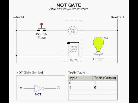
Logic Not Gate Tutorial With Logic Not Gate Truth Tablebasic

The Not Gate Logic Gates Electronics Textbook

Transistor Logic Not Gate Inverter

Cmos Gate Circuitry Logic Gates Electronics Textbook

Inverter Logic Gate Wikipedia

Activity Ttl Inverter And Nand Gate Analog Devices Wiki

Inverter Logic Gate Wikipedia

Logic Not Gate Tutorial With Logic Not Gate Truth Tablebasic

Digital Electronics Logic Gates Basics Tutorial Circuit Symbols
Logic Not Function Digital Logic Gatesbasic Electronics Tutorials

The Not Gate Logic Gates Electronics Textbook

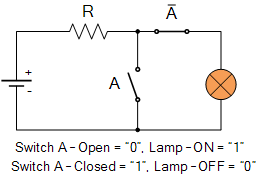
The Not Gate Inverter

Inverter Logic Gate Wikipedia

Digital Logic Not Gate
What Is The Working Principle Of Cmos Inverter Quora

5 4 Nmos And Pmos Logic Gates Introduction To Digital Systems

Not Gate Or Inverter From Reading Table
Logic Not Gate Tutorial With Logic Not Gate Truth Tablebasic

The Not Gate Logic Gates Electronics Textbook

Digital Logic Not Gate

Cmos And Ptl Hybrid Circuits A Circuit Design For An Xor Gate With

Transistor Logic Not Gate Inverter

A Cmos Inverter And A Single Load Capacitor Gate Output Current I O

Not Gate Circuit Basic Electronics Wiring Diagram

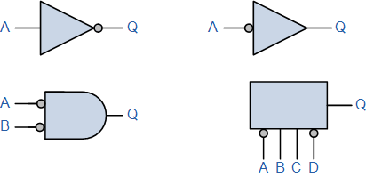
Basic Logic Gates
Logic Gates The Not Gate Youtube

Cmos Gate Circuitry Logic Gates Electronics Textbook

Aoi And Oai Complex Gates

Transistor Circuits

Single Phase Half Bridge And Full Bridge Inverter Circuit Using Matlab

Lessons In Electric Circuits Volume Iv Digital Chapter 3

Digital Logic Not Gate

Circuit Diagram Of Inverter And Nand Gate Download Scientific Diagram

How To Invert Logic Gate Input In Circuitikz Tex Latex Stack

Circuit Diagram Not Gate Basic Electronics Wiring Diagram

What Do You Mean By Logic Gates A Plus Topper

The Basic Elements Of Digital Circuits Mosfet Gate And The Logic

Nand Gate Operation Ece Tutorials

Logic Gates And Truth Table And Or Not Nor Nand Xor Xnor

Inverter Logic Gate Wikipedia

74ls04 Pinout Features Equivalent Examples Datasheet

Experiment 1 Multimeter Measurements On Dc Resistive Circuits

Solved The Circuit In Figure Is A Type Of Cmos Or And Invert G

The Not Gate Logic Gates Electronics Textbook

Small Logic Gates The Building Blocks Of Versatile Digital
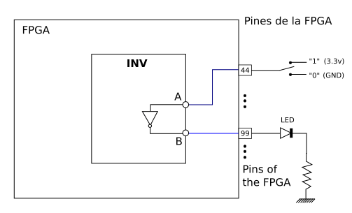
Chapter 3 Not Gate Inv Obijuan Open Fpga Verilog Tutorial Wiki
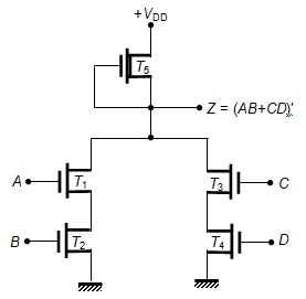
Nmos And Or Invert Gate Circuit Electronics And Communications

Solved The Circuit In Figure X14 21 A Is A Type Of Cmos

Not Gate Circuit Basic Electronics Wiring Diagram

Inverter Logic Gate Wikipedia
