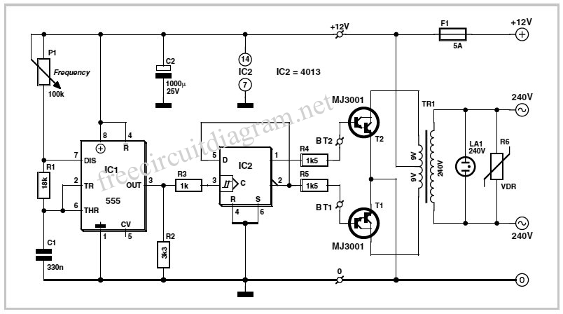
Inverter Circuit Diagram Using Cd4047
100watt inverter circuit inverter circuits are among the easiest circuits to build for newbies.
Inverter circuit diagram using cd4047. This is the circuit diagram of 3000w power inverter 12v to 230v modified sinus capable to deliver about 3000w 230v ac output from 12v input. This is the inverter circuit for professional only. Simple low power inverter circuit 12v dc to 230v or 110v ac diagram using cd4047 and irfz44 power mosfet gallery of electronic circuits and projects providing lot of diy circuit diagrams robotics microcontroller projects electronic development tools. 100 watt inverter circuit diagram parts list design tips.
Inverters are devices that convert dc input supply to ac alternating current. They are also called power inverters. This dc to ac converter is very simple and contains no more than 12 components. Ic cd4047 generates a signal with frequency 5060hz who paraphase exits 10 and 11 is fed to the gates of mosfet transistors irfz44.
Transistors alternately commute primary winding of the transformer floor and appears on the secondary ac voltage of. These modified inverters produce a square wave and these are not used to power delicate electronic equipments. Here a simple voltage driven inverter circuit using power transistors as switching devices is build which converts 12v dc signal to single phase 220v ac. Hi its my first time build an inverter neh thing is the circuit diagram of the pwm doesnt seem to make sense as it shows the ic with all sided pins while the one at the bottom and the one i bought is two sided and also it doesnt say as to the porality of the ic or where the lines to the mosfets come from.
Could you please grant me. This is inverter circuit 500w 12vdc to 220v 50hz. It easy to make and low cost. Using basic parts transistors 2n3055 ic 4047.


+Circuit+diagram+using+CD4047+and+IRFZ44+power+MOSFET.png)


+Circuit+diagram+using+CD4047+and+IRFZ44+power+MOSFET.png)


