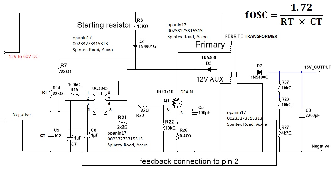
Ferrite Core Inverter Circuit Diagram
Since it is non contact the heating process does not contaminate the material being heated.
Ferrite core inverter circuit diagram. Using two switch topology. When developing a welding inverter i applied forward inverter with two switches topology. Here the input line voltage traverses through the emi filter further smoothing with big capacity. Few days ago gohz made a 24v 2000w power inverter in home sharing some design schematics and circuit diagrams.
The picture was taken in short circuited. Automotive led timing light a useful timing strobe can be constructed using high brightness leds and a few common components. Ignition pulses from the number 1 cylinder high tension lead are used to trigger the circuit via a home made inductive pickup. The post discuses the how to make a 3 phase inverter circuit which can be used in conjunction with any ordinary single phase square wave inverter circuit.
Using the sg3525 pwm controller explanation and example. Circuit diagram schematic of push pull converter. N12 understanding broad band ferrite transformers used in solidstate power amplifiers by la7mi stein torp 1994. Transformer with two windings and iron core.
Transformer with three windings. The dots show the relative configuration of the windings. Induction heating is a non contact heating process. It uses high frequency electricity to heat materials that are electrically conductive.


