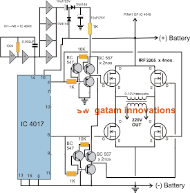
Full Bridge Inverter Circuit
The power circuit diagram for the single phase full bridge inverter is shown in the figure a.

Full bridge inverter circuit. Among the different existing inverter topologies the full bridge or the h bridge inverter topology is considered to be the most efficient and effective. In this post we try to investigate how to design a sg3525 full bridge inverter circuit by applying an external bootstrap circuit in the design. The two basic inverter circuits commonly used are the full bridge also called as h bridge and the half bridge. A less common inverter circuit used in induction heating is the quarter bridge or single switch inverter.
There are mainly two types of single phase inverter. Half bridge inverter and full bridge inverter. Here we will study how these inverters can be built and will simulate the circuits in matlab. In this article we are going to study a simple full bridge inverter circuit using ic 555 which can be built by any new hobbyist within few hours and see it running successfully.
Single phase full bridge inverter for r l load. A single phase square wave type voltage source inverter produces square shaped output voltage for a single phase load. Such inverters have very simple control logic and the power switches need to operate at much lower frequencies compared to switches in some other types of inverters.


