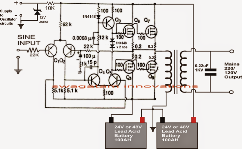
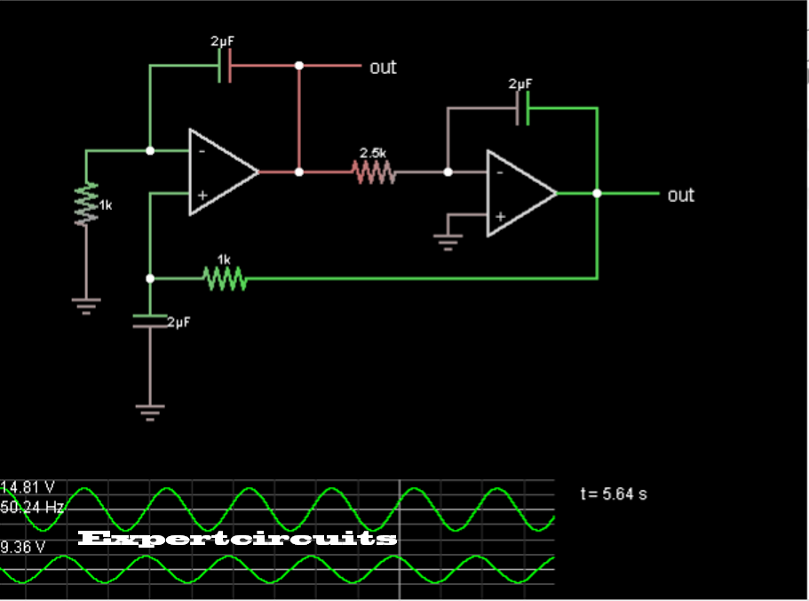
500 Watt Pure Sine Wave Inverter Circuit Diagram
Typical home wiring has the neutral and ground wires tied together.
500 watt pure sine wave inverter circuit diagram. 100 watt inverter circuit diagram parts list design tips. Inverters are devices that convert dc input supply to ac alternating current. They are also called power inverters. Here is a simple but powerful stable and efficient schematic diagram for a 500w modified sine wave inverter circuit.
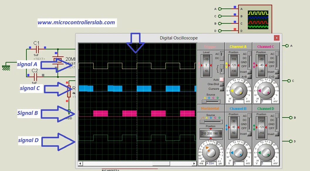
Originally i used a 555 timer and a cd4017 decade counter to produce the modified sine wave but then i thought a simple pic micro controller with its internal clock would produce a stable 50hz60hz frequency without the need. Home power inverter is to provide uninterrupted power to run household electric devices. These inverters for home are available in different voltage and load capacities. Simple low power inverter circuit 12v dc to 230v or 110v ac diagram using cd4047 and irfz44 power mosfet gallery of electronic circuits and projects providing lot of diy circuit diagrams robotics microcontroller projects electronic development tools.
Using the sg3525 pwm controller explanation and example. Circuit diagram schematic of push pull converter. Less than two decades ago it made sense to purchase a propane refrigerator for two reasons. Solar electricity was prohibitively expensive.
Ac power inverters were expensive inefficient and most made a poor quality electricity such as the infamous modified sine wave. Low cost power inverters modified sine wave actually have power being generated on both the live and neutral lines.


.jpg)


