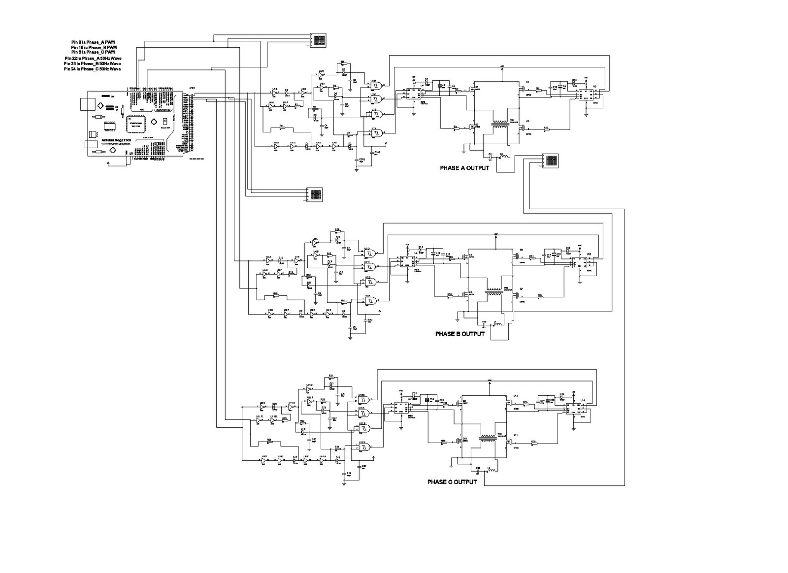
3 Phase Inverter Circuit
Application designed for indoor installation in commercial or industrial applications.
3 phase inverter circuit. Choose various source and load parameters number of devices to parallel heat sink parameters etc. Live simulated operating and switching waveforms are generated as well as data tables showing calculations for loss and junction temperature allowing you to compare the effect of parameter variations or the operation of different parts directly. 3 phase inverter system with. 1200v rated igbt module of current ratings from 50a 200a.
Supporting multiple vendors 7 reinforced isolated igbt gate drivers iso5852s with working voltage isolation of 15kvrms with minimum cmti of 50 kvms. This design provides a reference solution for a three phase inverter rated up to 10kw designed using the reinforced isolated gate driver ucc21530 reinforced isolated amplifiers amc1301 and amc1311 and mcu tms320f28027. A power inverter or inverter is an electronic device or circuitry that changes direct current dc to alternating current ac. The input voltage output voltage and frequency and overall power handling depend on the design of the specific device or circuitry.
This is the circuit diagram of 3000w power inverter 12v to 230v modified sinus capable to deliver about 3000w 230v ac output from 12v input. This is the inverter circuit for professional only. Phase splitter circuit new phase inverter schematic. Phase splitters are essential in push pull audio amplifiers.
Hmi already made this circuit inverter and i read some questions that need help. The resistor wout wattage is all 14 watt cfrand the 1n414b you may use 1n4148 for fast switchingand also the diode dx2a it means its a diodeyou may use 1n5402and to be able to have an output fix to 500 watt the transistor should be 14 pcs and it means 7. 100 watt inverter circuit diagram parts list design tips. Inverters are devices that convert dc input supply to ac alternating current.
They are also called power inverters.


